ODP Embedded Controller Track Overview
The Embedded Controller (EC) track is designed for individuals who are interested in developing and integrating embedded controller systems within the Open Device Partnership (ODP) framework. This track focuses on the design, implementation, and testing of embedded controllers, which are essential components in modern computing devices. Readers will learn how ODP supports creating robust EC solutions that enhance device functionality, improve power management, and ensure system reliability.
Embedded Controller
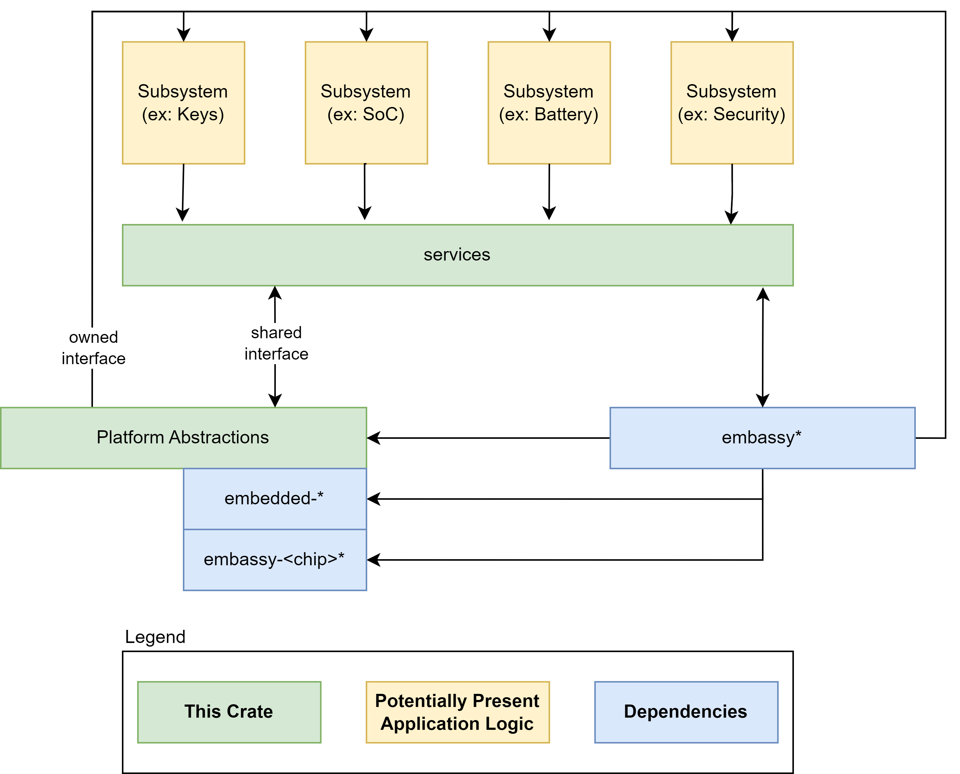
An Embedded Controller is typically a single SOC (System on Chip) design capable of managing a number of low-level tasks.
These individual tasked components of the SOC are represented by the gold boxes in the diagram. The ODP Support for Embedded Controller development is represented in the diagram in the green boxes, whereas third party support libraries are depicted in blue.
Component modularity
A Component can be thought of as a stack of functionality defined by traits (A trait in Rust is analogous to an interface in other common languages).
For the functionality defined by the trait definition to interact with the hardware, there must be a HAL (hardware abstraction layer) defined that implements key actions required by the hardware to conduct these tasks. These HAL actions are then controlled by the functional interface of the component definition.
The component definition is part of a Subsystem of functionality that belongs to a Service.
For example, a Power Policy Service may host several related Subsystems for Battery, Charger, etc. Each of these Subsystems have Controllers to interact with their corresponding components. These Controllers are commanded by the Service their Subsystem belongs to, so for example, the power policy service may interrogate the current charge state of the battery. It does so by interrogating the Subsystem Controller which in turn relies upon the interface defined by the component Trait, which finally calls upon the hardware HAL to retrieve the necessary data from the hardware. This chain of stacked concerns forms a common pattern that allows for agile modularity and flexible portability of components between target contexts.
flowchart TD
    A[e.g. Power Policy Service<br><i>Service initiates query</i>]
    B[Subsystem Controller<br><i>Orchestrates component behavior</i>]
    C[Component Trait Interface<br><i>Defines the functional contract</i>]
    D[HAL Implementation<br><i>Implements trait using hardware-specific logic</i>]
    E[EC / Hardware Access<br><i>Performs actual I/O operations</i>]

    A --> B
    B --> C
    C --> D
    D --> E

    subgraph Service Layer
        A
    end

    subgraph Subsystem Layer
        B
    end

    subgraph Component Layer
        C
        D
    end

    subgraph Hardware Layer
        E
    end
Secure vs Non-Secure
Communication between Subsystems may be considered to be either a "Secure" channel for data communication or a "Non-Secure" channel. An implementation may use more than one transport for different controller and controller service needs.
Data communication with the embedded controller can be considered an owned interface because it is implemented within the EC architecture itself. It may also tie into an external communication bus such as SPI or I2C for data exhanges between other MCUs or the host, but for purposes of communicating between its own subsystems, it is an internally implemented construct.
A "Secure" transport is one that can validate and trust the data from the channel, using cryptographic signatures and hypervisor isolation to insure the integrity of the data exchanged between subsystems. Not all such channels must necessarily be secure, and indeed in some cases depending upon the components used it may not even be possible to secure a channel. The ODP approach is agnostic to these decisions, and can support either or both patterns of implementation.
Depending upon the hardware architecture and available supporting features, a secure channel may incorporate strong isolation between individual component subsystems through memory access and paging mechanisms and/or hypervisor control.
Two similar sounding, but different models become known here. One is SMM, or "System Management Mode". SMM is a high-privilege CPU mode for x86 microcontrollers that EC services can utilize to gain access. To facilitate this, the SMM itself must be secured. This is done as part of the boot time validation and attestation of SMM access policies. With this in place, EC Services may be accessed by employing a SMM interrupt.
For A deeper dive into what SMM is, see How SMM isolation hardens the platform
Another term seen about will be "SMC", or "Secure Memory Control", which is a technology often found in ARM-based architectures. In this scheme, memory is divided into secure and non-secure areas that are mutally exclusive of each other, as well as a narrow section known as "Non-Secure Callable" which is able to call into the "Secure" area from the "Non-Secure" side.
Secure Memory Control concepts are discussed in detail with this document: TrustZone Technology for Armv8-M Architecture
SMM or SMC adoption has design ramifications for EC Services exchanges, but also affects the decisions made around boot firmware, and we'll see these terms again when we look at ODP Patina implementations.
Hypervisor context multiplexing
Another component of a Secure EC design is the use of a hypervisor to constrain the scope of any given component service to a walled-off virtualization context. One such discussion of such use is detailed in this article
The Open Device Partnership defines:
- An "owned interface" that communicates with the underlying hardware via the available data transport .
- We can think of this transport as being a channel that is considered either "Secure" or "Non-Secure".
- This interface supports business logic for operational abstractions and concrete implementations to manipulate or interrogate the connected hardware component.
- The business logic code may rely upon other crates to perform its functions. There are several excellent crates available in the Rust community that may be leveraged, such as Embassy.
- Synchronous and asynchronous patterns are supported.
- No runtime or RTOS dependencies.
An implementation may look a little like this:
Embedded Controller Architecture
The construction of a typical component under the control of a service subsystem looks as follows:
flowchart LR
    A[Some Service<br><i>Service initiates query</i>]
    B[Subsystem Controller<br><i>Orchestrates component behavior</i>]
    C[Component Trait Interface<br><i>Defines the functional contract</i>]
    D[HAL Implementation<br><i>Implements trait using hardware-specific logic</i>]
    E[EC / Hardware Access<br><i>Performs actual I/O operations</i>]

    A --> B
    B --> C
    C --> D
    D --> E

    subgraph Service Layer
        A
    end

    subgraph Subsystem Layer
        B
    end

    subgraph Component Layer
        C
        D
    end

    subgraph Hardware Layer
        E
    end
When in operation, it conducts its operations in response to message events
sequenceDiagram
    participant Service as Some Service
    participant Controller as Subsystem Controller
    participant Component as Component (Trait)
    participant HAL as HAL (Hardware or Mock)

    Service->>Controller: query_state()
    Note right of Controller: Subsystem logic directs call via trait
    Controller->>Component: get_state()
    Note right of Component: Trait implementation calls into HAL
    Component->>HAL: read_some_level()
    HAL-->>Component: Ok(0)
    Component-->>Controller: Ok(State { value: 0 })
    Controller-->>Service: Ok(State)

    alt HAL returns error
        HAL-->>Component: Err(ReadError)
        Component-->>Controller: Err(SomeError)
        Controller-->>Service: Err(SomeUnavailable)
    end
A core pattern of the ODP architecture is one of Dependency Injection. The service and subsystem Traits define the functional contract of the component, while the HAL implementation provides the hardware-specific logic. This allows for a clear separation of concerns and enables the component to be easily tested and reused across different platforms. Components are eligible to be registered for their subservice if they match the required traits.
flowchart TD
    subgraph Component
        A[Needs Logger and Config]
    end

    subgraph Framework
        B[Provides ConsoleLogger]
        C[Provides NameConfig]
        D[Injects Dependencies]
    end

    B --> D
    C --> D
    D --> A
EC Component Model
A component that implements a specification and depends upon a HAL interface.
flowchart TD
    A[Component]
    B[Specification Trait]
    C[HAL Trait]

    A --> B
    A --> C
A component is housed within a subsystem, which is controlled by a service. The service orchestrates the component's behavior and manages its lifecycle.
flowchart TD
    A[__Controller__ <br/> Implements Service Interface Trait]
    B[__Device__ <br/> Implements Component Type Trait]
    C[__Component__ <br/> Implements Specification Trait]

    A --> B
    B --> C
Component interactions are generally initiated in response to message events. The controller receives a message, which it routes to the component. The component then calls into the HAL to perform the requested operation.
flowchart TD
    A[__Service Layer__ <br/> e.g. _Controller_]
    B[__Device Layer__ <br/> _Wrapped Component_]
    C[__Component Layer__ <br/> _Handles Message_]

    M["Incoming Message"] --> A
    A -->|calls _handle_| B
    B -->|calls _handle_| C
Runtime Behaviors of an Embedded Controller
Component code is typically executed as an asynchronous task invoked by Embassy Executor. A component reacts to events that are produced at higher levels of the Embedded Controller logic, through one or more policy manager tasks.
Tasks are generally event-driven actions dispatched in response to messages.
Messages are conveyed through a comms implementation. Events may be handled exclusively be a single component or reacted to by more than one component.
Messages are queued and dispatched in order but are handled asynchronously. Signaling may be required to enforce an ordered flow.
A component is wrapped within a defined Device wrapper that implements the traits that identify and control the implemented device type. The Controller for the device reacts to various events issued at the direction of policy manager logic, and in turn invokes the component hardware in appropriate response.
sequenceDiagram
    participant Policy as Policy Manager Task
    participant Comms as Comms Dispatcher
    participant Ctrl as Controller
    participant Dev as Device Wrapper
    participant Comp as Component (Implements Trait)

    Policy->>Comms: Emit Message (e.g. BatteryEvent)
    Comms->>Ctrl: dispatch_message()
    Ctrl->>Dev: handle()
    Dev->>Comp: perform_action()
    Comp-->>Dev: Result
    Dev-->>Ctrl: Response
    Ctrl-->>Comms: Ack or follow-up message
Embedded Controller Service Registration
Embedded Controller components and services in ODP are statically composed at build time but must be registered with the service infrastructure to become discoverable and operational during execution.
This registration model allows each policy domain (e.g. power, thermal, charging) to own and manage the devices associated with it.
Registration Pattern
Pseudocode (concept only)
The registration flow is: construct → init services → register.let battery = BatteryDevice::new(DeviceId(1)); // ... // in an async task function embedded_services::init().await; embedded_services::power::policy::register_device(&battery).await.unwrap();This omits static allocation (
StaticCell), executor wiring for async tasks, and controller setup, for clarity.
Realistic skeleton (matches the sample projects)
Refer to the Battery implementation example or the examples in the embedded-services repository for more concrete examples.
#![allow(unused)]
fn main() {
// statically allocate single ownership
static BATTERY: StaticCell<MockBatteryDevice> = StaticCell::new();

// Construct a device handle
let battery = BATTERY.init(MockBatteryDevice::new(DeviceId(1)));

// In an async context, initialize services once, then register the device
embedded_services::init().await;
embedded_services::power::policy::register_device(&battery).await.unwrap();

// Controller setup is covered in the next section.
}
Semantics note: In ODP, “Device” types are handles to a single underlying component; the service runtime serializes access. Introducing the controller simply gives policy logic a dedicated handle to act on; it does not create a second owner of the hardware.
Bringing in the Controller
#![allow(unused)]
fn main() {
let controller = CONTROLLER.init(
    MockBatteryController::<&'static mut MockBattery>::new(battery.inner_battery())
);
}
The controller is given a handle to the inner MockBattery (inner_battery()), not a second owner of the hardware. All access is serialized through the service runtime.
What Registration Enables
| Feature | Enabled by Registration |
|---|---|
| Message Routing | The comms system delivers events to services |
| Task Spawning | Services are polled and run by the executor |
| Feature Exposure | Subfeatures (e.g. fuel_gauge) declared via trait contracts |
| Test Visibility | Services and devices can be observed in tests |
flowchart TD
    A[Component<br/>_Implements Trait_] --> B[Device Wrapper]
    B --> C[Controller<br/>_Implements Service Trait_]
    C --> D[SERVICE_REGISTRY]
    D --> E[Policy Manager<br/>_via Comms_]
    D -->|_Provides_| F[Async Task Execution]
Figure: Service Registration and Runtime Execution
Devices are wrapped and managed by controllers. These are registered into the service registry, which exposes them to both the message dispatcher and the async runtime for polling and task orchestration.
Message Dispatch and Service Binding
Once a controller is registered, the service registry allows the comms system to route incoming events to the correct service based on:
- The device ID
- The message type
- The controller's implementation of the
handle()function (as defined by ServiceTraits)
When a message is emitted (e.g. BatteryEvent::UpdateStatus), the comms channel looks up the appropriate service and dispatches the message.
Where ServiceTraits represent the service traits that define a Controller action,
implementation may look something like this (in this case, ServiceTraits defines a function
named handle, and it calls upon a local function defined in the device implementation):
#![allow(unused)]
fn main() {
impl ServiceTraits for BatteryController {
    async fn handle(&mut self, msg: Message) -> Result<()> {
        match msg {
            Message::Battery(BatteryEvent::UpdateStatus) => {
                self.device.update().await
            }
            _ => Ok(()),
        }
    }
}
}
This provides a flexible pattern where services are matched to message types through trait implementations and static dispatch. No dynamic routing or introspection is used — behavior is known at compile time.
Static Composition, Dynamic Coordination
While all services and components are statically bound into the final binary:
- Message routing and task polling occur dynamically
- Controllers only receive messages for devices they were registered to manage
- Multiple services can be registered independently and coexist without conflict
This pattern supports:
- Easy testing with mocks or alternate HALs
- Additive subsystem design (battery, charger, thermal)
- Isolated debugging of service behavior
EC Services
The Embedded Controller is responsible for an increasing number of tasks that are meant to be always available, independent of the main CPU. The scope of these EC services often goes beyond hardware device concerns alone. These services often need to be exposed to the Operating System and Application layers so that higher-level monitoring and control designs can interact to inspect conditions or configure operating parameters.
Conceptually, any number of services could be exposed to the Operating System in this way. The Windows Operating System specifies a particular set of EC Services that it requires.
These Windows services are discussed in the Embedded Controller Interface Specification
Windows-specific management features such as the Microsoft Power Thermal Framework (MPTF) implementation notes are relevant to this discussion also.
EC Services Architecture
Communication Pathways
flowchart TD
    A[Host OS or Firmware]
    B[ACPI Interface / Mailbox / HID]
    C[EC Service Dispatcher]
    D[Subsystem Controller - Battery, Thermal, etc.]

    A --> B
    B --> C
    C --> D
Figure: EC Service Entry Points Host platforms interact with EC services through one or more communication pathways. These may include ACPI-defined regions, mailbox protocols, or vendor-defined HID messages. The EC processes these via service dispatch logic.
Messaging Exchange Format (Conceptual)
sequenceDiagram
    participant Host
    participant EC

    Host->>EC: Request {Service ID, Command, Payload}
    EC-->>Host: Response {Status, Data}
Figure: Message Exchange
The diagram above illustrates the basic message handshake.
This table explains the field data exchanged:
Field Description Service ID Identifies target subsystem Command Specific operation to perform Payload Data required for operation Status Result of operation Data Optional result values
Secure and Non-Secure Implementations
In the diagram below, the dark blue sections are those elements that are part of normal (non-secure) memory space and may be called from a service interface directly. As we can see on the Non-Secure side, the ACPI transport channel has access to the EC component implementations either directly or through the FF-A (Firmware Framework Memory Management Protocol).
Secure implementation architecture can be seen in the upcoming Security discussion.
flowchart TD
    A[Untrusted Host OS]
    B[Trusted Runtime Services]
    C[EC Service Gateway]
    D[EC Subsystems]

    A -.->|Filtered Access| C
    B -->|Secure Channel| C
    C --> D
Embedded Controller Security
Naturally, as the scope of concerns that fall to the Embedded Controller has grown, security for these features becomes paramount.
ODP provides support for hardware-enforced isolation of the Embedded Controller Service Interface enforced with Hafnium for hypervisor control.
EC Services
Embedded controller services are available for the operating system to call for various higher-level purposes dictated by specification. The Windows Operating system defines some of these standard services for its platform.
These service interfaces include those for:
- debug services
- firmware management services
- input management services
- oem services
- power services
- time services
Services may be available for operating systems other than Windows.
OEMs may wish to implement their own services as part of their product differentiation.
EC Service communication protocols
With a communication channel protocol established between OS and EC, operating system agents and applications are able to monitor and operate peripheral controllers from application space.
This scope comes with some obvious security ramifications that must be recognized.
Implementations of ODP may be architected for both Secure and Non-Secure system firmware designs, as previously discussed.

In the diagram above, the dark blue sections are those elements that are part of normal (non-secure) memory space and may be called from a service interface directly. As we can see on the Non-Secure side, the ACPI transport channel has access to the EC component implementations either directly or through the FF-A (Firmware Framework Memory Management Protocol).
FF-A
The Firmware Framework Memory Management Protocol (Spec) describes the relationship of a hypervisor controlling a set of secure memory partitions with configurable access and ownership attributes and the protocol for exchanging information between these virtualized contexts.
FF-A is available for Arm devices only. A common solution for x64 is still in development. For x64 implementations, use of SMM is employed to orchestrate hypervisor access using the [Hafnium] Rust product.
In a Non-Secure implementation without a hypervisor, the ACPI connected components can potentially change the state within any accessible memory space. An implementation with a hypervisor cannot. It may still be considered a "Non-Secure" implementation, however, as the ACPI data itself is unable to be verified for trust.
In a fully "Secure" implementation, controller code is validated at boot time to insure the trust of the data it provides. Additionally, for certain types of data, digital signing and/or encryption may be used on the data exchanged to provide an additional level of trust.
Secure EC Example
Consult the Secure EC Services Specification for more explanation and a sample implementation discussion.
Embedded Controller Exercises
For a hands-on walkthrough for creating key Embedded Controller components, such as Battery, Charger, and Thermal devices, please see the Component Examples