Thermal component Diagrams
Our Thermal component subsystem will be pretty simple and basic. It will be comprised of one temperature and one fan.
More sensors and more fans or other thermal mitigation hardware solutions could be added to any given real-world implementation using the same patterns.
flowchart LR
  %% overall left-to-right so the two lanes sit side-by-side
  %% ─────────────────────────────────────────────────────────

  subgraph SVC[Service Layer]
    svc[Service<br/><i>message / request</i>]
  end

  subgraph SUBSYS[Thermal Subsystem]
    direction LR

    %% ── Sensor lane ───────────────────────────────────────
    subgraph SENSOR[Sensor path]
      SC[Sensor Controller<br/><i>policy, hysteresis</i>]
      ST[Thermal Traits<br/><code>TemperatureSensor</code><br/><code>TemperatureThresholdSet</code>]
      SM[MockSensor Device<br/><i>device wrapper</i>]
    end

    %% ── Fan lane ──────────────────────────────────────────
    subgraph FAN[Fan path]
      FC[Fan Controller<br/><i>policy, spin-up</i>]
      FT[Fan Traits<br/><code>Fan</code><br/><code>RpmSense</code>]
      FM[MockFan Device<br/><i>device wrapper</i>]
    end
  end

  subgraph HW[Virtual / Hardware State]
    HS[VirtualTemperatureState<br/><i>temperature + thresholds</i>]
    HF[VirtualFanState<br/><i>rpm</i>]
  end

  %% wiring
  svc --> SC
  svc --> FC

  SC --> ST --> SM --> HS
  FC --> FT --> FM --> HF
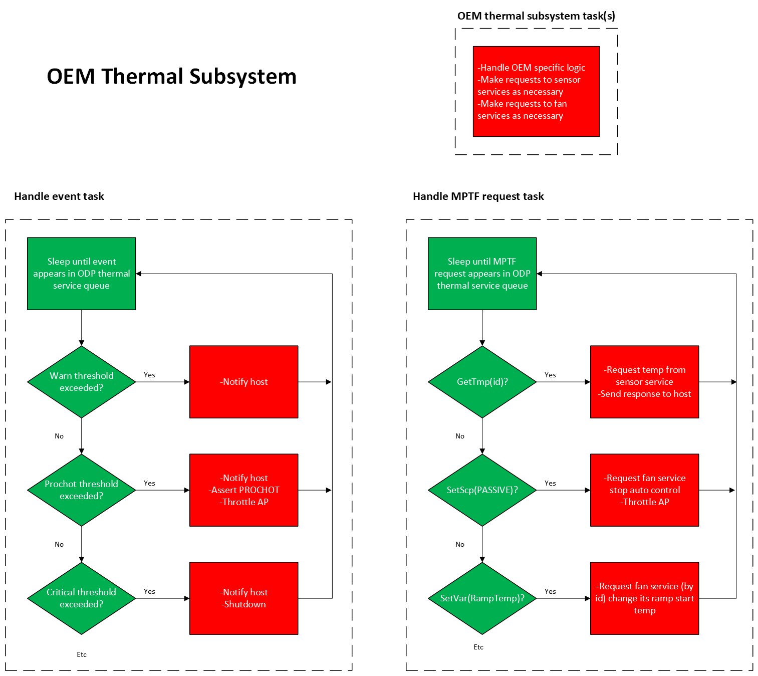
When in operation, it conducts its operations in response to message events according to behavior logic that we will define and test here.